Geometrical Transformations
In order to model objects we need to be able transform objects in 3D space.
Transformations involve the translation, scaling and rotation of objects in either 2D or 3D space.
Objects are defined by a set of points. It is the points that are transformed.
Using transformations we need only model any object exactly once. We can then transform it to several locations in world space. For example, when modelling a chess board's players, we need only make one pawn and transform it to the sixteen pawn starting positions on the board.
We can use transformations to move an object from one place to another, such as moving a player during the chess game.
We can use transformations to scale and rotate objects.
2D Transformations
2D transformations consist of translation, scaling or rotation of objects in 2D space.
Translation
A point in the xy-plane can be translated to a new position by adding a translation amount to the coordinates of the point.
To translate a point P(x,y) by a distance Dx units parallel to the x-axis and Dy units parallel to the y-axis to a new point P'(x',y') we apply the transformation matrix:
P' = P + T
or
[x', y'] = [x, y] + [Dx, Dy]
An object can be translated by applying the same translation to all the defining points of that object.
Scaling
To scale an object Sx times in the direction of the x-axis and Sy times in the direction of the y-axis we apply a scaling transformation matrix to each of the object's defining points.
The scaling matrix is defined as:
![]()
So
![]()
Unfortunately scaling is performed about the origin, so any scaling also has the side effect of a translation.
Rotation
Rotating the x and y components of a 2D point by an angle θ in an anti-clockwise direction about the origin is achieved using the two formula below:
x' = x cos q - y sin q
y' = x sin q + y cos q
In matrix form the same rotation can be achieved by multimplying the point by the matrix shown below:
![]()
The above equation performs rotations in an anti-clockwise direction. To rotate in a clockwise manner through an angle -θ , we substitute for:
cos(-θ ) = cosθ
and
sin(-θ ) = -sinθ
As with scaling, the rotation is about the origin and gives an unwanted translation as a side effect.
Homogeneous Coordinates
It would be preferable if all three transformations were mathematically similar. In the above, translation is treated differently to scaling and rotation.
Using homogenous coordinates we can express all three transformations as matrix multiplications.
The respective homogeneous translation, scaling and rotation matrices are:
Translation

Scaling

Rotation

Composition of 2D Transformations
Rather than applying translation, scaling and rotation matrices independently to the defining points of an object we can combine the three to form a general transformation matrix. Applying the transformation matrix to the object is the same as applying the sequence of translates, scales and rotates.
Using transformation matrices we can eliminate the side effect from both scaling and rotation.
To scale an object about some CENTRE OF GRAVITY point C(x,y) we multiply each of its defining points by the composite transformation matrix formed by:
1. Translate, so that the centre of gravity, C, is at the origin;
2. Scale;
3. Translate so that the centre of gravity point at the origin returns to its original position, C.
The transformation matrix is:


A similar approach is used for rotating about some point C(x,y).
For rotation the transformation matrix is:


Combining Scaling and Rotation
A common transformation might be to scale and rotate an object about the same point, C, and then to translate the object so that C is at a final position C'. This involves:
1. Translate so that C is at the origin;
2. Scale;
3. Rotate;
4. Translate so that the point at the origin is now at C'.
NOTE: Scaling and Rotation are NOT commutative. To get the correct transformation (in the above example) we must perform the scale before the rotate.
The non-cummutivity of scaling and rotating is shown in the following example.
The diagram below shows the (tall narrow) rectangle defined by the four corner points (-1,4), (1,4), (1,-4) and
(-1,-4) and the centre of gravity (0,0).
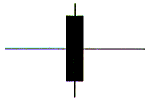
The result of firstly scaling this rectangle by a factor of (2,1/2) and then rotating it by 90o about the origin is shown in the diagram below.
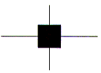
The result of firstly rotating this rectangle by 90o about the origin and then scaling it by a factor of (2,1/2) is shown in the diagram below.
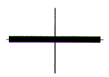
Clearly, scaling and rotation are NOT commutative.
Efficiency Considerations

By examining the final structure of any transformation matrix we find that the upper left 2 * 2 matrix is the composite scale and rotate matrix, while m31 and m32 are the composite translations. The right most column will always have the values 0 0 1.
Using this information we simplify the actual maths uses to perform a transformation to
|
x' |
= x*m11 |
+ y*m21 |
+ m31 |
|
y' |
= x*m12 |
+ y*m22 |
+ m32 |
This is a reduction from nine multiplies and nine additions to four multiplies and four additions. This is very significant, especially if we consider that an object might consist of hundreds or even thousands of points.
3D Transformations
3D homogeneous coordinates are an extension of 2D homogeneous coordinates.
Translation

Scaling

Rotation
2D rotation is simply rotation about the z-axis. In 3D we must allow for rotation about each of the three axes: x, y and z.
Rotation about the x-axis

Rotation about the y-axis

Rotation about the z-axis

The order in which 3D rotations are performed is not commutative. For example, a rotation about the y-axis followed by a rotation about the x-axis will give a different result than rotating about the x-axis followed by a rotation about the y-axis.
Worked Example  What is the result of applying a rotation of 90 about the y-axis followed
by a rotation of 90 about the x-axis on the point (1, 0, 0)?
ANS: (0, 1, 0)

What is the result of applying a rotation of 90 about the x-axis followed
by  a rotation of 90 about the y-axis on the point (1, 0, 0)?
ANS: (0, 0, -1)
Efficiency Considerations
As with 2D, any 3D transformation is of the form:
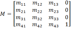
Using this information we simplify the actual maths uses to perform a transformation to:
|
x' |
= x * m11 |
+ y * m21 |
+ z * m31 |
+ m41 |
|
y' |
= x * m12 |
+ y * m22 |
+ z * m32 |
+ m42 |
|
z' |
= x * m13 |
+ y * m23 |
+ z * m33 |
+ m43 |
This is a reduction from sixteen multiplies and twelve additions to nine multiplies and nine additions, which, again, is very significant if we consider that an object might consist of hundreds or even thousands of points.
Coordinate Systems
The ability to transform objects freely about a 3D space leads to a convenient way of modelling objects. We can think of each object as being built in its own coordinate system, called an object coordinate system. The object can be built to a suitably convenient scale. For example we might build a unit cube. This can be latter transformed into boxes of any position, size and orientation within any other coordinate system.
We can apply a transformation to any object so that it can be used as part of the definition of another object. For example, we can transform our unit cube into a brick coordinate system. Here, the unit cube is suitably scaled. The brick, in turn can be transformed many times into the object coordinate system of a house. The individual bricks are translated and rotated into position so as to build the model of a house.
To combine several objects in the final model we need simply transform each object into a world coordinate system.
An object is invisible in other objects' coordinate systems because we simply don't reference the invisible object.
Left Handed and Right Handed Coordinate Systems
We can define a world or object coordinate system using either the Left Hand Rule (where the positive z-axis goes into the page) or the Right Hand Rule (where the positive z-axis comes out from the page). Most graphics books use the Right Hand Rule, simply because it is the standard mathematical convention. However, the Left Hand Rule is intuitively easier to comprehend as it gives the natural interpretation that larger z-values are further from the viewer. For this reason, we shall define our 3D coordinate systems using the Left Hand Rule in these notes.
NOTE that the exact same matrix mathematics is used for both left and right handed systems. The only differences the two systems are:
- the direction of the positive z-axis (left handed goes into the page and right handed goes out of the page)
- the direction of rotation (use either left hand or right hand to indicate direction of rotation)
Switching between Left and Right Handed Coordinate Systems
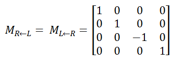
The direction of the positive z-axis is dependent on whether we are using the Left Hand Rule or the Right Hand Rule. In these notes we use the Left Hand Rule. In the Left Hand Rule, the positive z-axis goes into the page and in the Right Hand Rule, the positive z-axis comes out from the page. Conversion between a right handed and left handed coordinate system is achieved by multiplying each contol point by the matrix:
Left Handed Coordinate System
In the Left Hand Rule, the direction of rotation about any of the three principle axes is anti-clockwise around the positive axis. If you imagine your left hand being clenched around the axis with your thumb pointing in the positive direction of the axis, then your four clenched fingers point in the direction of rotation about the axis.
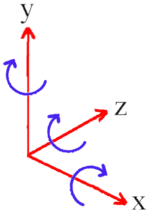
Positive rotations about the:
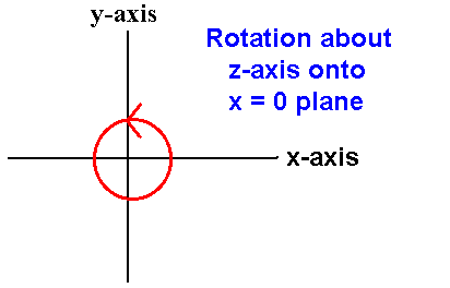
- z-axis are towards the x = 0 plane
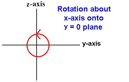
- x-axis are towards the y = 0 plane
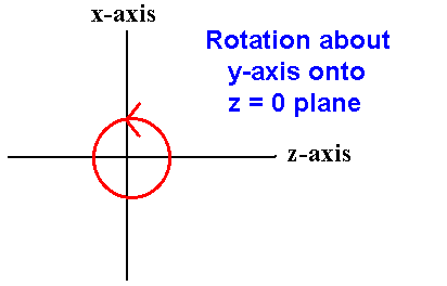
- y-axis are towards the z = 0 plane
The direction of rotation for each of the three principle axes is show in the three diagrams below. In all three diagrams, positive rotations are always in an anti-clockwise direction as you look along the positive axis of rotation away from the origin.
Negative Angle Rotations

From the sin and cos waves shown in the diagram above, we can see that negative angle rotations (i.e. clockwise rotations in the left handed coordinate system) are achieved by making the following substitutions:
- sin(-α) = -sinα
- cos(-α) = cosα
We can plug these substitutions into the various translation, scaling and rotation matrices that we have already developed.
Worked Example
What is the result of the rotating the point (0, 4, 0) by the sequence of the following three rotations:
- -340º about x (α)
- then 150º about y (β)
- then -130º about z (θ)
- sinα = 0.342
- cosα = 0.94
- sinβ = 0.5
- cosβ = -0.866
- sinθ = -0.766
- cosθ = -0.6428
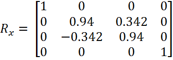

 (0, 4, 0) * Rx = (0, 3.76, 1.368)
(0, 3.76, 1.368) * Ry = (0.684, 3.76, -1.1847)
(0.684, 3.76, -1.1847) * Rz = (2.4405, -2.9409, -1.1847)
ANS: (2.4405, -2.9409, -1.1847)
Instead of multiplying the point by each matrix, we could have pre-multiplied the three rotations and then multiplied the point by the matrix that results from the pre-multiplication. Multiplying (0, 4, 0) by the above matrix gives the rotated point
(2.4404, -2.9408, -1.1848)
Allowing for rounding errors at 4 decimal places, this is the same answer as is got multiplying the point by each matrix in turn.Rotation about an Arbitrary Axis
As described earlier in this chapter, the rotation of an object about an arbitrary centre of gravity point, C, is a reasonably straightforward task. However, it is often required to rotate an object about some arbitrary axis (where the axis has been defined by its two end points).
How do we do such a rotation?
We can only rotate objects about the three principle axes (i.e. the x, y and z-axes). Therefore, any other rotation must be simplified into a combination of rotations about the three principle axes.
If we can transform an arbitrary axis so that it lies on one of the principle axes, then we can easily rotate an object about it (by rotating the object about the principle axis that the transformed arbitrary axis lies on).
Therefore, if we can develop a transformation that transforms an arbitrary axis onto one of the principle axes, then we can rotate an object about the arbitrary axis.
Rotation about an Arbitrary Axis
We wish to rotate an object by an angle α about an arbitrary axis defined by the two points P1 and P2.
Step 1:
Translate by -P1, so that P1 is at the origin:
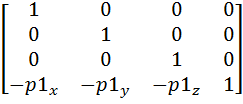
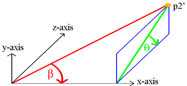
The translation will cause P2 to be translated to P2', as shown in the diagram below.
Step 2:
Rotating P2' by an angle θ about the x-axis will cause the arbitrary axis to be rotated onto the y=0 plane.
cosθ = z / S1
sinθ = y / S1
where: S1 = Ö (y² + z²)

In order to rotate an arbirary axis onto a principle plane, we need the sin and cos of the angles θ and β. The sin and cos needed to rotate any point about about a principle axis onto its associated principle plane can be got from the point's coordinates.
We shall consider rotations about the z-axis onto the x = 0 plane. All results obtained will apply equally to rotations about the x-axis onto the y = 0 plane or about the y-axis onto the z = 0 plane.
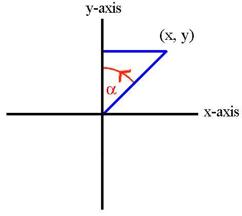


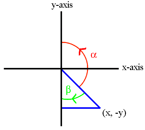


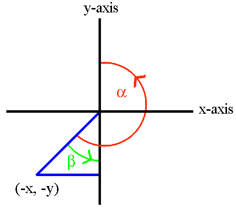


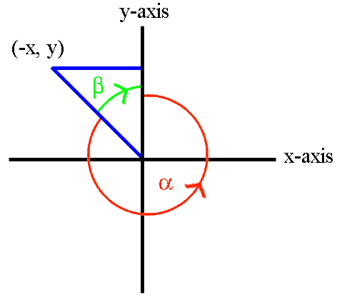


The four diagrams above show the necessary rotation about the z-axis onto the x = 0 plane for each of the four quadrants. The only difference between the formulae for the four quadrants is the ± sign of x and y.
In the four sets of formulae above, we note that the ± sign of x and y used in the fout quadrant's formulae always matches the ± sign of the x and y coordinates for that quadrant. Therefore, by using the exact x and y coordinates (including the ± sign information), the above four sets of formulae can be replaced by the one generalised set of formulae below.


We can explain why the same sin and cos formulae work for all four quadrants by observing the sin and cos waves, as show in the diagram below.

If we compare the sign of the sin and cos against the sign of the four quadrants of the x-axis versus y-axis we get a one to one correspondence. This is show in the diagram below.
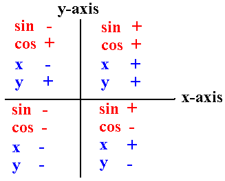
Having the one generalised set of formulae means that we do not need to worry about the ± sign of the x, y or z coordinates for the translated point p2'.
Although all three coordinates of the translated P2' are shown as being positive in the diagram below, in a real application one or more of the coordinates might be negative. Nothing extra needs to be done to deal with negative coordinates.

Step 3:
Next, rotating by an angle ß about the y-axis will cause the arbitrary axis to be rotated onto the x-axis.
cosß = x / S2
sinß = S1 / S2
where: S2 = Ö (x² + y² + z²)

Step 4:
At this stage, we can perform the desired rotation by an angle α about the x-axis (which is co-incident with the arbitrary axis).

Once the rotation is performed we must transform the arbitrary axis back to its original position. This is done by:
Step 5:
Rotation by an angle -ß about the y-axis.

Note: For Step 5 (and Step 6) we rotate using negative angles. As explained in the earlier section on "Negative Angle Rotations", the values for the sin and cos are:
- sin(-β) = -sinβ
- cos(-β) = cosβ
Step 6:
Followed by rotation by an angle -θ about the x-axis.

Step 7:
Followed by a translation P1.
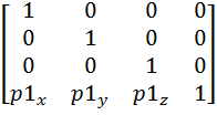
Worked example:
What is the anti-clockwise 90° rotation of the point (10, 8, 6) about the arbitrary axis defined by the two points (0, 0, 0) and (5, 0, 10)? Give your answer correct to four decimal places.Solution
Shortcut 1: Because one of the two endpoints in on the origin, we do not need to perform step 1) or step 7). Shortcut 2: Because the y coordinate of the second point is 0, we do not need to perform step 2) or step 6). If we do not spot these two shorcuts, we shall find the affected matrices will be the identity matrix. Multiplying a vector or matrix by the identity matrix does not change the original vector or matrix's value.Step 1:
Translate by -P1, so that P1 is at the origin:P1x = P1y = P1z = 0
The translation will cause P2 to be translated to P2', as shown in the diagram below.
NOTE:In the diagram above, we show all three coordinates of the translated P2' as being positive. In a real application one or more of the coordinates might be negative. Nothing extra needs to be done to deal with negative coordinates.
Step 2:
Rotating P2' by an angle θ about the x-axis will cause the arbitrary axis to be rotated onto the y=0 plane. S1 = Ö (y² + z²) = Ö (0² + 10²) = 10 cosθ = z / S1 = 10/10 = 1 sinθ = y / S1 = 0/10 = 0

Step 3:
Next, rotating by an angle ß about the y-axis will cause the arbitrary axis to be rotated onto the x-axis. S2 = Ö (x² + y² + z²) = Ö (5² + 0² + 10²) = 11.1803 cosß = x / S2 = 5 / 11.1803 = 0.4472 sinß = S1 / S2 = 10 / 11.1803 = 0.8944

Step 4:
At this stage, we can perform the desired rotation by an angle α about the x-axis (which is co-incident with the arbitrary axis).cos (90º) = 0 sin (90º) = 1
Once the rotation is performed we must transform the arbitrary axis back to its original position. This is done by Steps 5, 6 and 7.
Step 5:
Rotation by an angle -ß about the y-axis.
Note: For Step 5 (and Step 6) we rotate using negative angles. As explained in the earlier section on "Negative Angle Rotations", the values for the sin and cos are: sin(-ß) = -sinß cos(-ß) = cosß
Step 6:
Followed by rotation by an angle -θ about the x-axis.

Step 7:
Followed by a translation P1.
Multiplying out the matrices gives:
Multiplying the point [10, 8, 6] by the above matrix gives:
ANS: [-2.7552, 6.2608, 12.3776]
Copyright Derek O' Reilly, Dundalk Institute of Technology (DkIT), Dundalk, Co. Louth, Ireland.