Copyright Derek O'Reilly, Dundalk Institute of Technology (DkIT), Dundalk, Co. Louth, Ireland.
Projection Transformations
To display any 3D modelled scene on a computer monitor we must project the
3D modelled scene through a 2D view window onto the computer monitor's 2D
viewport.
A view window represents a view that we have into the modelled world. A view
window is equivalent to a window in a room. If we are in a room with a single
window, then our view of the world outside the room contains only those objects
that are visible through the window. This is also true for a view window.
Only those objects that are visible through the view window will be visible
on the computer monitor's viewport
A view window can be placed in any position and orientation in a 3D modelled
scene.
The plane that the view window lies on is called the view plane.
Types of Projection
There are two types of projection:
-
Parallel Projection;
-
Perspective Projection.

For parallel projection, all projection rays are parallel to a direction
of projection ray.
In parallel projection, projected angle and line measurements are directly
proportional to the original 3D measurements. Therefore, relative measurements
can be made between the various angles and line measurements of a parallel
projected image. For this reason, parallel projection is used in computer
aided design (CAD) packages.

For perspective projection there is one centre of projection (COP), from
which all projection rays originate. Projection rays originate at the centre
of projection, intersect the view plane and pass through the objects.
In perspective projection, no information about the original angle or line
measurements can be calculated from the projected image.
However, because they have perspective, perspectively projected images look
more realistic than do parallel projected images. Therefore, perspective projection
is used in everything other than CAD packages.
Parallel Projection
There are two types of parallel projection.

In orthographic projection the direction of projection and the normal to
the view plane are the same (i.e the projection is normal to the view plane).

In oblique projection the direction of projection is NOT EQUAL to the view
plane normal.
Orthographic Projection
Orthographic projection is a form of parallel projection.
A simple type of orthographic projection is a front, top or side projection,
where the view plane is the z, x or y axis respectively. Such projections
would only show one face of a cube placed at the origin.
An orthographic projection, where the view plane is NOT one of the three
principle axes is called an axonometric orthographic projection.
Using axonometric projection we can view more than one face of an object
at any time.
Oblique Projection
Oblique projection is also a form of parallel projection.
In oblique projection the direction of projection and the view plane normal
are not the same.
Perspective Projection
In 3D, objects viewed in the distance appear to be smaller than those viewed
up close. This is known as perspective. Perspective projection is the geometry
associated with perspective.
In perspective projection the length of a line is related to its distance
from the centre of projection. Two objects of EQUAL height but at different
distances from the centre of projection (e.g. two houses, one of which is
twenty metres away, the other of which is two hundred metres away) will be
projected with DIFFERENT heights onto the view plane. NO information regarding
line lengths can be got from the projected image.
Likewise, as the perspective projection rays are all travelling in different
directions from the centre of projection, no information regarding angle sizes
can be got from the projected image.
Vanishing Points
In perspective projection everything converges into one or more vanishing
points, beyond which we see nothing.
Although we are used to dealing with only one vanishing point, there may
be up to three vanishing points:- one for each of the x, y and z principle
axes that is cut by the view plane.
View Volume
With both parallel and perspective projection it is often desirable to limit
the size of the view volume.
With perspective projection, the projection of objects that are too close
to the window appear to be nothing more than a random collection of disjoint
lines. Also with perspective projection, objects that are very far from the
window appear as a blob. Not only can no discernible features be taken from
these objects, but they also blur the other objects.
A front and a back clipping plane are given as distances from the view plane.
The front and back clipping distances are measured along the view plane normal.
The various objects in the world need to be clipped against the view volume
prior to projecting the view volume onto the view window.
Visible and Obscured Points On Projection Rays
No matter how many objects are intersected by a given perspective or parallel
projection ray, only one intersection point can be visible. The colour information
of the visible intersection point IS the projection from 3D down to 2D for
the given projection ray.
The visible intersection point is the one that is nearest the view plane
along the line of the projection ray. The visible point will obscure all intersection
points behind it on the projection ray.
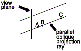
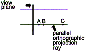
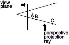
In each of the following diagrams, the intersection point A obscures the
intersection points B and C, and so only A is visible.
Determining the Intersection Point of a Projection
Ray and an Object
A projection ray that is cast through a view window might intersect one or
more objects in a 3D modelled scene. If the projection ray does intersect
one or more objects in the modelled scene, then the object that intersects
the projection ray nearest (i.e. nearest when measured along the projection
ray) to the view window must be visible through the view window. The colour
information of this intersection point should be projected onto the 2D view
window. The visible intersection point will obscure all other intersection
points for a given projection ray.
In order to use projection, we need to have a method of determining the intersection
point of any projection ray and object in the modelled scene.
Mathematically, a projection ray is a line. For any type of object that we
wish to project we must develop an algorithm to determine the intersection
point between that object and a line.
NOTE: The only objects described in
these notes are polygons.
Projection ray/polygon intersection is described in detail in the chapter
on Efficient
Polygon Rendering.
The Normalised View Volume
Projection from a 3D modelled scene onto a view plane involves placing the
nearest intersection point's colour information for each projection ray onto
the view plane.
For an orthographic parallel projection onto the plane defined by z = 0 the
nearest intersection point is the intersection point with the smallest z value.
Calculation of the nearest intersection point for all other projections (i.e.
orthographic projections other than onto z=0, all oblique projections and
all perspective projections) is computationally expensive during run time.
It is possible to transform any parallel or perspective projection for a
modelled scene so that the projection becomes an orthographic projection onto
the z=0 plane and the modelled world is remapped accordingly.
Such a transformation can be applied ONCE to each control point in a modelled
scene prior to rendering. This is mathematically less computationally expensive
than the calculation of each intersection point during run time.
As well as transforming the modelled scene so that its projection is onto
the z=0 plane, we can modify the modelled scene so as to remove all objects
from in front of its front clipping plane and from behind its back clipping
plane.
We can apply a further transformation so as to place the clipped, modelled
scene inside the unit cube view volume.
The complete transformation of the modelled scene and its parallel or perspective
projection is referred to as a projection transformation.
The transformed, clipped, unit cube, modelled scene is called a normalised
view volume.
From Normalised View Volume to Monitor's Viewport
Rendering a normalised view volume onto a computer monitor's viewport is
relatively straight forward.
We cast one orthographic projection ray through the view window to represent
each pixel of the computer monitor's viewport.
If the viewport is, for example, 10 pixels wide and 5 pixels high, then we
must cast 10 orthographic projection rays across by 5 orthographic projection
rays down the view window. As the view window is guaranteed to be 1 wide by
1 high, we must cast an orthographic projection ray every 1/10 across by 1/5
down through the view window.
Worked Example
Mapping from Normalised View Volume onto a Viewport
Map from the normalised view volume onto the computer monitor's viewport
whose top left corner pixel coordinate is (xMin,yMin) = (10,5) and whose
bottom left corner pixel coordinate is (xMax,yMax) = (50,15).
The pixel width (w) and pixel height (h) of the viewport are:
w = 50 - 10

  = 40

h = 15 - 5

  = 10
Therefore we must generate 40 * 10 (400) projection rays into the normalised
view volume.
Placing the projection rays in proportion to the width and height of the
computer monitor's viewport means there must be one projection ray at every
1/w (1/40) across the normalised view volume and one projection ray at every
1/h (1/10) down the normalised view volume. This gives the required 400 projection
rays.
The colour information returned by casting each of the 400 projection rays
is then mapped onto each projection ray's equivalent pixel on the computer
monitor's viewport.
An algorithm to map from normalised view volume to computer monitor's viewport
is shown below:
Render(int xMin, int yMin, int xMax, int yMax)
{
   int   w,h;
   float u,v,uStep,vStep;

   w     = xMax - xMin;
   h     = yMax - yMin;
   uStep = 1/w; // step size across
   vStep = 1/h; // step size down
   y = yMin;
   for (v = 0;v < 1;v += vStep) // stepping down the view window
   {
      x = xMin;
      for (u = 0,u < 1; u += uStep)   // stepping across one row of the view window
      {
         colour = SmallestZColour(); // see note
         PutPixel(x,y,colour);
         x++;
      }
      y++;
   }
}
NOTE: The smallest intersection point IS the visible intersection point,
and so its colour is the colour to be displayed. The chapters on Polygons
discuss how to obtain a projection ray/object intersection point.
Projection Transformation to the Normalised View Volume
We need to develop two projection transformation matrices:
-
one parallel projection transformation matrix, which
will work for both orthographic and oblique projection;
-
a perspective projection transformation matrix.
These two projection transformation matrices can be used to transform any
modelled scene and parallel or perspective projection into the normalised
view volume (which can then be rendered onto the view window and finally mapped
to the computer monitor's viewport).
Parallel Projection Transformation
The following parameters are required to derive the parallel projection transformation
matrix:
-
top left (tl), bottom left (bl) and bottom
right (br) corner points of the view window;
-
direction of projection vector (DOP); Within these
notes we shall assume that this has been made into a unit vector.
-
front (F) and back (B) clipping distance.
The steps involved in building the parallel projection transformation matrix
are:
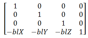
1. Translate bl to the origin
2. Rotate view window so that br lies on the x-axis, tl lies
on the y-axis and the view plane normal lies on the minus z-axis
3. Shear so that direction of projection becomes normal the z-axis
4. Translate to place the front clipping plane on the z = 0 plane
5. Scale the view volume into the unit cube
1) Translate
bl to the origin
2) Rotate
the view window so that br lies on the x-axis, tl lies on the
y-axis and the view window normal (VWN) lies on the minus z-axis
This involves a rotation around Rx, followed by a rotation around Ry and finally a rotation around Rz
- first, rotate around the x-axis to bring the VWN into the y=0 plane
- second, rotate around the y-axis to align VWN with the positive z-axis
- third, rotate around the z-axis to align br with the positive x-axis and tl with the positive y-axis
However, because the matrices are orthonormal, it is possible to do all three rotations using only one matrix, as shown below.
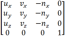
where ux is the first element of u , et cetera.
To get the values for u , v and n we apply
the following equations:
u is the unit directional vector from bl to br
v is the unit directional vector from bl to tl
n is the unit directional vector that is normal to v and u (i.e. cross product, v X u)
Worked Example
Given:
bl = (2, 1, -3)
br = (2, -1, -3)
tl = (2, 1, -9)
Map the view window defined by the above three points
so that br lies on the x-axis, tl lies on the y-axis and
the view window normal (VWN) lies on the z-axis
Step 1) Translate bl to the origin.
 Multiplying bl, tl br by the above matrix gives:
bl' = (0, 0, 0)
br' = (0, -2, 0)
tl' = (0, 0, -6)
Step 2) Rotate the view window so that br lies on the x-axis, tl lies on the
y-axis and the view window normal (VWN) lies on the minus z-axis
We could perform a rotation about each of the x, y and z axes in turn to
align the view window with them. However, a more efficient approach is possible
because we are dealing with orthonormal matrices.
The efficient composite rotation matrix that rotates the view window so that br lies on the
x-axis, tl lies on the y-axis and the VWN lies on the minus z-axis is:
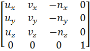
where ux is the first element of u, uy is the second element of u, et cetera.
To get the values for u , v and n we apply the following equations:
u is the unit directional vector from bl to br
v is the unit directional vector from bl to tl
n is the unit directional vector that is normal to v and u (i.e. v X u)
(i) Calculating u
u is the unit directional vector from bl to br
bl = (2, 1, -3)
br = (2, -1, -3)
directional vector is br - bl
u = (2, -1, -3) - (2, 1, -3)
= (0, -2, 0)
unit direction vector is
u = (0, -1, 0)
(ii) Calculating v
v is the directional vector from bl to tl
bl = (2, 1, -3)
tl = (2, 1, -9)
directional vector is tl - bl
v = (2, 1, -9) - (2, 1, -3)
= (0, 0, -6)
unit direction vector is
v = (0, 0, -1)
(iii) Calculating n
n is the directional vector that is normal to v and u (i.e. v X u)
v = (0, 0, -1)
u = (0, -1, 0)
n = v X u
= (0, 0, -1) X (0, -1, 0)
= (0*0 - -1*-1, -1*0 - 0*0, 0*-1 - 0*0)
= (-1, 0, 0)
unit direction vector is
n = (-1, 0, 0)
-n = (1, 0, 0)
Plugging u, v and n into the matrix R gives
 Multiplying bl', tl' and br' by the above matrix gives:
bl'' = (0, 0, 0)
tl'' = (0, 6, 0)
br'' = (2, 0, 0)
We can see from these results that:
bl has been mapped onto the origin
tl has been mapped onto the y axis
br has been mapped onto the x axis
The above matrix will also map n onto the minus z-axis.
n' = (0, 0, -1)
Worked Example (a) What is the result of the rotating the points (0, 0, 0,), (6, 0, 0) and(0, 4, 0) by the
sequence of the following three rotations:
- -340º about x (α)
- then 150º about y (β)
- then -130º about z (θ)

ANS:
(0, 0, 0) maps onto (0, 0, 0)
(6, 0, 0) maps onto (3.3402, 3.9804, -3)
(0, 4, 0) maps onto (2.4404, -2.9408, -1.1848)
(b) Map the view window defined by the three points below,
so that
br lies on the x-axis,
tl lies on the y-axis and
the view window normal (VWN) lies on the z-axis
- bl = (0, 0, 0)
- br = (3.3402, 3.9804, -3)
- tl = (2.4404, -2.9408, -1.1848)
Unit direction vector u = (3.3402/6, 3.9804/6, -3/6)
= (0.5567, 0.6634, -0.5)
Unit direction vector v = (2.4404/4.001, -2.9408/4.001, -1.1848/4.001)
= (0.6099, -0.735, -0.2961)
n = u × v = (uY*vZ - uZ*vY, uZ*vX - uX*vZ, uX*vY - uY*vX)
= ((0.6634*-0.2961) - (-0.5*-0.735),
(-0.5*0.6099) - (0.5567*-0.2961),
(0.5567*-0.735) - (0.6634*0.6099))
= (-0.5639, -0.1401, -0.8138)
-n = (0.5639, 0.1401, 0.8138)
Plugging u, v and n into the matrix R gives

Multiplying the three points and n by the above matrix gives:
bl = (0, 0, 0)
br = (6.0001, 0.0001, -0.0002)
tl = (0, 4.0007, -0.0001)
n = (0, 0, -0.9999)
Allowing for rounding errors correct to four ecimal places,we can
see from these results that:
- bl has been mapped onto the origin
- br has been mapped onto the x axis
- tl has been mapped onto the y axis
- n has been mapped onto the -z axis
3) Shear so that direction of projection becomes normal the z-axis.
Shearing translates the direction of projection so that it coincides with
the z-axis.

Shearing maps y1 onto y1' and y2 onto y2'.
Note: the z coordinates of the two
points are not changed by the shear.
The shearing of any y coordinate of a point onto the z = 0 plane is shown
in the diagram below:
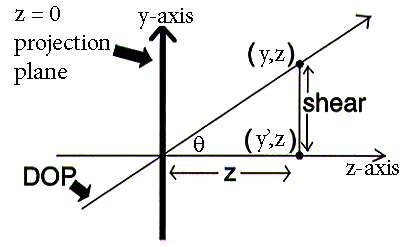
From the diagram above:
   tanθ  = shear / z
=> shear = z * tanθ

The shear of y onto y' is:
y' = y - shear

Substituting z * tanθ for shear gives:
x' = x - z * tanθ

As the DOP is normalised:
tanθ= DOPy / DOPz
The shearing of the x coordinate of a point onto z = 0 plane is similar
to the above:
x' = x - z * tanσ
The shear matrix is:

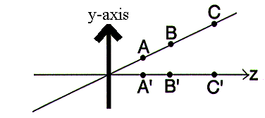
NOTE: Shearing maintains relative depths.
If point A obscures points B and C on the original projection ray, then A'
will obscure point B' and C' on the sheared ray.
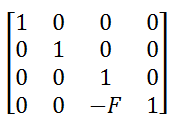
4) Translate to place the front clipping plane
on the z = 0 plane.
Translate along the z-axis by a distance -F to remove the view volume
that lies in front of the front clipping plane.
The translation matrix is:
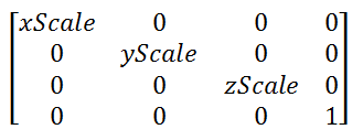
5) Scale the view volume into the unit cube.
Scale by the respective factors along each of the axes x, y and z:
xScale= 1/(uMax - uMin)
yScale= 1 / (vMax - vMin)
zScale= 1 / (B - F)
The scale matrix is:
Perspective Projection
The following are required to derive the perspective projection transformation
matrix:
-
top left, bottom left and bottom right corner points of
the view window;
-
the point that defines the Centre of Projection;
-
front and back clipping distance.
The VRP is set as the centre of the view window. It is calculated from the
parameters given as:

The steps involved are:
-
Translate the COP to the origin
-
Rotate view window so that br is parallel to the x-axis, tl is parallel to the y-axis and the view plane normal is parallel to the minus z-axis
-
Shear so that the VRP lies on the positive z-axis
- Scale so that the six planes defining the view volume
become: x = z, x = -z, y = z, y = -z, z = VRPz - F, z = 1
-
Shear the unit pyramid into the parallelopipe of size
2 wide (x) by 2 high (y) by 1 deep (z)
-
Translate to place the front clipping plane on the z=0
plane.
-
Scale the view volume into the unit cube.
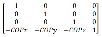
1) Translate the COP to the origin
This is similar to step 1 from the Parallel Projection.
2) Rotate view window so that br is parallel to the x-axis, tl is parallel to the y-axis and the view plane normal is parallel to the minus z-axis
This is similar to step 2 from the Parallel Projection.

3) Shear so that the VRP lies on the positive z-axis
This is similar to the step 3 from the Parallel Projection.
A shear is applied to the VRP, where the VRP is at the centre of the window. The centre point of the view window is calculated as shown below:
centreX = (trx + blx) / 2
centreY = (try + bly) / 2
centreZ = (trz + blz) / 2
The shear onto the x = 0 plane is:
x' = x- z * tans
The shearing onto the y = 0 plane is:
y' = y - z * tanθ
As with the parallel projection, we do not need to shear z.
The shear matrix is:

The diagram below shows the result of shearing the VRP onto the z-axis.
4)Scale so that the six planes defining the view volume
become: x = z, x = -z, y = z, y = -z, z = VRPz - F, z = 1
The above six faces will result in a pyramid frustum that has as it two ends the front and back clipping planes and as its four sides the pyramid with a slope of 1 in the x and y directions and a slope of -1 in the -x and -y directions.
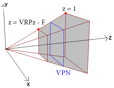
To achieve the above transformation, we need to do two scales.
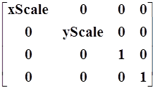
4a) Scale in x and y, so that the sloped planes of the view volume have a unity slope.
To get a unity slope:
* scale in x and y, so that the sloped planes of the view volume have a slope of 1.
* scale in -x and -y, so that the sloped planes of the view volume have a slope of -1.
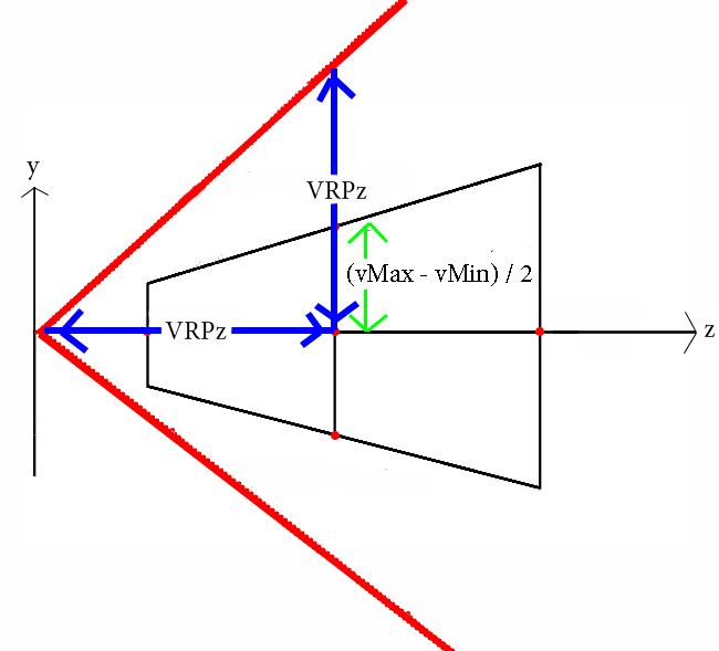
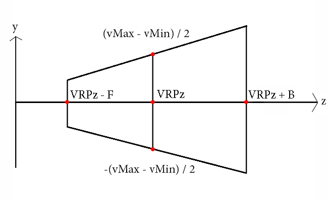
From the diagram above, the scale needed in y to get a unity slope is:
yScale =  VRPz / [(vMax - vMin) / 2]
       = (2 * VRPz) / (vMax - vMin)
Likewise,
xScale = = (2 * VRPz) / (uMax - uMin)
The same scale will scale the negative x and y sloped planes of the view volume so that they have a slope of -1.
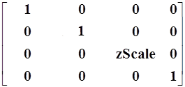
4b) Scale in z to make (VRPz + B) have a length of 1, while keeping the unit slope of the sloped planes of the view volume.
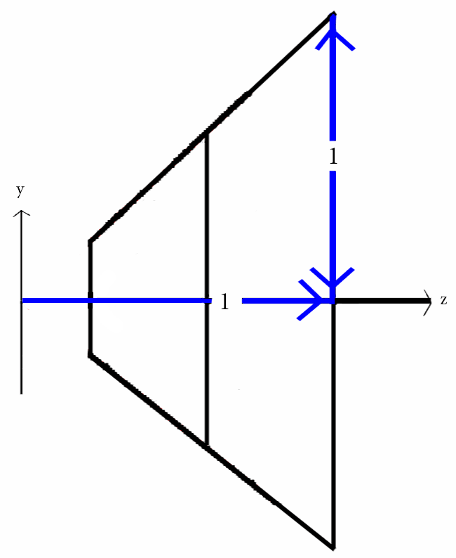
From the diagram above:
zScale = 1 / (VRPz + B)
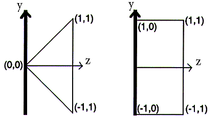
5) Shear the unit pyramid into the parallelopipe
of size 2 wide (x) by 2 high (y) by 1 deep (z)
Shearing the unit pyramid into the parallelopipe of size 2 wide (x length)
by 2 high (y length) by 1 deep (z length) is shown in the diagram below.
The shearing of y onto y' is derived as follows:
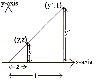
From the diagram above:
|
|
y/z |
= y' / 1 |
|
=> |
y' |
= y / z |
|
|
|
= y * 1/z |
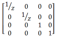
Using the formula y' = y * 1/z will mean that:
·
an object that is 1/4 units along z will have its y value divided by 1/1/4
(i.e multiplied by 4);
·
an object that is 1/2 units along z will have its y valued multiplied by 2;
·
an object that is at the back clipping plane (a distance of 1 units along
z) will be multiplied by 1 to give no change.
The multiplication by 1/z causes the perspective projection of more distant
objects to be smaller than the perspective projection of closer objects. The further an object is from the projection plane, the
larger its z coordinate will be, hence the smaller its projection onto the
projection plane will be.
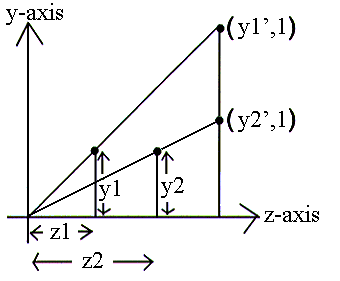
In the above diagram y1 = y2. However, because z1
< z2 the mapping of y1 onto the projection plane
is larger than the mapping of y2 onto the projection plane.
Similarly
The shear is only operated on the x and y coordinates, so that z remains
unchanged. Therefore:
z' = z
|
(x',y',z') |
= (x/z, y/z, z) |
|
|
|
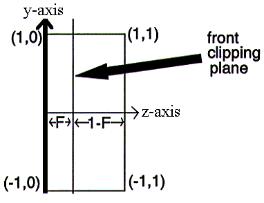
6) Translate to place the front clipping plane
on the z = 0 plane.

8) Scale the view volume into the unit cube.
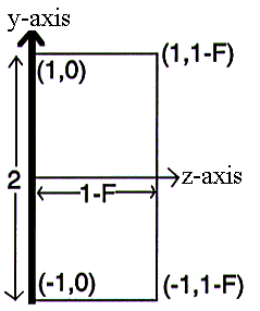
The width (x length) and height (y length) of the translated parallelopipe
both equal 2. Therefore, scale both x and y by a factor of 1/2.
The depth (z length) of the translated parallelpipe is 1-F.
Therefore scale by a factor of 1/(1-F) in the direction of z.
|
xscale |
= 1/2 |
|
yscale |
= 1/2 |
|
zscale |
= 1/(1-F) |

Copyright Derek O' Reilly, Dundalk Institute of Technology (DkIT), Dundalk, Co. Louth, Ireland.


 Multiplying bl', tl' and br' by the above matrix gives:
bl'' = (0, 0, 0)
tl'' = (0, 6, 0)
br'' = (2, 0, 0)
We can see from these results that:
bl has been mapped onto the origin
tl has been mapped onto the y axis
br has been mapped onto the x axis
The above matrix will also map n onto the minus z-axis.
n' = (0, 0, -1)

 Multiplying the three points and n by the above matrix gives:
bl = (0, 0, 0)
br = (6.0001, 0.0001, -0.0002)
tl = (0, 4.0007, -0.0001)
n = (0, 0, -0.9999)
Allowing for rounding errors correct to four ecimal places,we can
see from these results that:


